This is the part when I look back on how I planned my work, and see how I could have done better, and what I already did well.
To be brutally honest, my plan was partially perfection, and partially disastrous. On the one hand, I knew exactly what I wanted to do with my animation and why I was using each individual camera shot/action/etc. However at the same time I had absolutely no clue HOW I was going to implement all of these decision into Maya.
The reason I had no clue how to implement my ideas was down to the fact that - due to various life events - I had been completely unable to attend all but one Modelling&Animation lecture in the entirety of the second half of the semester. As such, my knowledge of animating is only what I've learned from reading on the VLE. This means anything I didn't learn from that is a tool I can't use and ultimately, I've been left with the bare minimum of skills to complete a working animation.
A lot of my animation will have to be done in key frames and with Belzier curves. These are two of the few (a.k.a: only) methods I know for animation objects as of this time. during the actual creation of my animation, I might be able to learn another to aid my creation.
I cannot really go into more detail about what I feel I did right with planning then I have already. I know exactly what I want to happen in the animation, I know exactly what camera angles/sizes/movements I want in each segment of the animation and I know why I'm doing it. I even know what music I want to use on the animation and - if my calculations are right - the animation should even sync up with the music! (For reference, It's this: https://www.youtube.com/watch?v=NKZKzINMSGk)
I can see my lack of knowledge causing a few problems for my 'vision'. For starters, I cannot figure out how to attach a camera to an object for the life of me. This will inevitably cause problems with panel 3 on my storyboard, where the idea was for the camera to follow the two smaller spaceships at they flew towards the imperial destroyer. However, if there's one thing I know I can do, it's get creative with limited options.
If I could re-do this half of the module all over again, I'd humbly request all outside life problems would NOT be present, so that I could actually attend lectures and be on time to finish my projects, rather than be forced to get an extension and complete all my work without peers around to offer help if I needed it. This was a huge inconvenience to everything and I really hope I don't have to deal with anything like that again for the rest of my life.
Wednesday, 31 December 2014
Monday, 15 December 2014
Unrelated, Course-based venting
So, as a random side-note that's not really relevent to this blog, I recently caught wind of the knowledge that our course representative was caught red-handed copying his models from some website. It's really disgraceful that the person who is supposed to represent us was caught cheating on a module that ultimately isn't too difficult to grasp.
If I'VE managed to not cheat despite all of the obstacles I've encountered this semester, then he has no excuse at all. I always thought he was a bit of a prick anyway and this just cements my opinion as fact.
If I'VE managed to not cheat despite all of the obstacles I've encountered this semester, then he has no excuse at all. I always thought he was a bit of a prick anyway and this just cements my opinion as fact.
Thursday, 20 November 2014
Camera Techniques
Before I continue with this post, I will be referring to my 'Storyboard' post a fair amount, so here is a direct link to this page: http://tomswonderfulassignmentblog.blogspot.com/2014/11/storyboard.html
In the first lecture after the completion of our 3D models, we studied how camera techniques are used in media to portray and display different things. A large majority of these could potentially come in use for the creation of my Animation.
Camera techniques can be split into 3 main areas: Angles, Shot sizes and Movement
Angles: A cameras angle is used to give a different feeling to a scene, a birds-eye view can be used to display a location to the viewer quickly and establish the feeling quickly, while an over-the-shoulder view is used to make the viewer see a scene from a certain characters perspective.
Another interesting angle that you can use is called the high-angle shot. While this is ultimately similar to the birds-eye view, it look down into the scene at a slight angle rather than directly from the top. This allows the viewer to see everything thats happening in a scene. I use this angle in frame 6 of my storyboard to easily display the acrobatic movement from the two smaller spaceships.
Shot Sizes: This is what most people would refer to as 'zoom'. A shot size simply refers to how close or far away the camera is from the main focal object. The names of a shot size is very much self-explanatory. A close-up is a really close to the object, probably even taking up the whole shot and is commonly used for showing emotion or other small details. A long shot is when the camera is a long way from the focal point, and is often used to show the scale of an object. I used a mix of both close up and long shot sizes in panel 1 of my storyboard in order to try and convey the imperial destroyer as being an enormous spaceship. I don't yet know if that will translate into the actual animation that well.
Movement: This is what a lot of my shots relied on. Movement is also self-explanatory in that is covers all forms of displacement, rotation and zooming. These can be used to create almost any desired effect, but movement is most effective when used for high-speed sequences or generally any sort of action-based media. I plan on using a lot of movement with my cameras in my animation, Panel 5 of my storyboard is probably the most notable example of this, as the plan is for the camera to start at the front of the imperial destroyer, and then quickly crab/pan towards and beyond the back of it as the other ships fly over/under it. Hopefully, speedy camera movement will create the effect of fast-moving spaceships, or at least appear to move faster than they actually are.
Thursday, 6 November 2014
Storyboard
Now that I've finished making my textures models, I now need to move on to the final section: The storyboards!
The storyboarding is necessary for a later part of this module, in which I will be doing a short animation featuring my models.

1: Imperial flies past, camera pans to follow
2: X-wing and headhunter swoop down and toward camera, camera remains static
3: Sprays lasers. pewpewpew
4: Lasers hit imperial. no damage
5: Xwing and headhunter loop over/under imperial
6: Xwing and headhunter loop around and fire more lasers
7: lasers hit booster, it explodes
8: Imperial falls out of sky, Xwing and headhunter fly off into distance, come in from off camera
Wednesday, 5 November 2014
Model Texturing
Now that we have made our three models, we need to texture them. Texturing is the necessary 'cheery of top' of the modelling that turns a lifeless, but accurate grey-scale model into a fully fledged model of a ship.
There are multiple different ways of texturing the ship, but we're going to be using a mix to get an accurate texture. For this Blog, I will be using my X-wing model to display the methods I'm going to use.
To get the first initial step done, we want to use 'block texturing' first to turn the entire ship into the most accurate 'general' colour. to do this, we need to select the entire ship and select 'Assign New Material'
This sets a new material on the entire ship, it then gives you a whole bunch of texturing options, which I can then edit as necessary. In this case, the most common colour of the ship is a cream/white colour, So we'll change the texture colour to fit that.
Now that the ship as a whole is close to the colour that we want, we just need to add some of the larger colour changes, like the silver nose/cockpit and the Black sections on the turbines. This is done by selecting the desired faces and doing the same 'Assign new material option we used for the whole ship earlier
Just like earlier, we can now change the colour of the texture to suit what we need it to be. in the case of the turbines, we want to change it fully to black. We do the same things with other parts of the ship, and we will end up with something like this
Now that we've got most of the basic colouring done, we can begin to go into detail. To do with, we need to select the faces that we wish to work on. First, I will be choosing the front of the ship, in order to add the red/yellow accents.
To do this, we first must select the faces we want to work on (These being the 3 long, thing faces that make up the front of the ship, the top half only) and selecting 'UV texture editor' and re-arranging the layout so only the 3 necessary faces are on the beige square.
Once we do this, we need to take a 'UV Snapshot' and save the image as a .jpeg file, so we can freely edit it. It was suggested to save it as a .tif file, and then edit it in Photoshop. However, I have absolutely no idea how to utilise photoshop effectively, and therefore decided to edit in paint, sacrificing detail in exchange of easy use.
Once you upload the picture to paint, you should see something similar to what we have in the above screenshot. all you need to do then is edit the picture (without deleted the pre-made border) in order to look similar to the ships original design. for my design it ended up looking like this
Once again, save the image. and we need to import back onto the faces of the model. If Everything has been done properly, the crudely done paint image should map itself perfectly to the model, and it did.
This is everything to the UV mapping. from here all I need to do is repeat this process a few times and then we're all finished!
Using the UV mapping seems convuluted for someone who are largely unused to it, and trying to use photoshop was almost impossible. However, theres always a workaround and workaround I did.
Final designs:
Friday, 31 October 2014
Third Ship: X-wing
The Third and final ship of my project will be an X-wing Aircraft. When looknig at my references images in the Moodboard, we can see that the X-wing looks functionally similar to the Z95 Headhunter in that is seems to be a small, agile fighter ship, but with a few key differences. The most obvious difference being that this aircraft actually has 4 wings instead of two, and they are aligned to form an X shape, as the name implies.
Due to the obvious similarities to the Headhunter, I'll be taking a different approach to this model. First off, I will be starting with my completed model of the Headhunter, instead of work from scratch. From a quick observation, we can see that the Turbines, wing and even the chassis for the X-wing are almost identical to the Headhunter, So I will be keeping those and just touching them up slightly in order to mould them to the X-wings design.
Here, we see that I have separated the important components from my Headhunter: A turbine, the Body, and one wing. If you remember my wings were one big poly last time. I've separated them into one wing by selecting it and choosing the 'Mirror Cut' tool on it in order to have only one wing.
 Now that I have my Needed components, We need to edit them. I'm going to start with the body, as that's the central part of the ship and can't really do much without it. The body of the X-wing is a lot longer and thinner than the body of the Headhunter, and does not have the huge cockpit, instead having a Cockpit that moulds much smoother into the body.
 As you can see, I have now created a much smaller, thinner body, Which now has the cockpit built into it. Now that we have the foundation built, We can add Our wings to it! If you look at the reference images of the Xwing, You'll see that the guns are set up in a fashion that wouldn't allow us to simply use the 2 wings together, so I had to split them up. But now that I've done that, I can place the wings in the correct fashion.
It's incredibly hard to see in this screenshot, but there are actually a few ridges on the wings. These are highly unwanted remnants of the previous extrusions that were the turbine supports on the Headhunter. And I have absolute no clue how to un-extrude the faces.


Due to the obvious similarities to the Headhunter, I'll be taking a different approach to this model. First off, I will be starting with my completed model of the Headhunter, instead of work from scratch. From a quick observation, we can see that the Turbines, wing and even the chassis for the X-wing are almost identical to the Headhunter, So I will be keeping those and just touching them up slightly in order to mould them to the X-wings design.
Here, we see that I have separated the important components from my Headhunter: A turbine, the Body, and one wing. If you remember my wings were one big poly last time. I've separated them into one wing by selecting it and choosing the 'Mirror Cut' tool on it in order to have only one wing.
It's incredibly hard to see in this screenshot, but there are actually a few ridges on the wings. These are highly unwanted remnants of the previous extrusions that were the turbine supports on the Headhunter. And I have absolute no clue how to un-extrude the faces.
Anyway, now that we have the wings in place, we can attach the turbines to it. The turbines from the headhunter are very similar to these, but there are a few tweaks that need to be made, just like with the chassis and the wings.
Here is the edited version of the turbines. the exhaust is now offcentre, aswell as the turbine as a whole having less indentation.
Now that I've gotten the turbine perfect, These need to be attached to the correct places, just like the wings. This part is easy enough but I also need to create the turbine supports on the wings, just like last time. This is relatively easy, but yet another slight tweak to the design of the Headhunter.
Here's the edited version of the wings, the underside has little to no change, but the side containing the turbine is slightly raised all the way along, albeit more discreetly right at the back.
Now that the wings have been altered, the third and final model is completed! Being able to use the assets of another model in this one saves a LOT of time overall, cutting production time greatly. Trying to undo areas that have been extruded is extremely hard though and an overall pain. I'd also recommend not ever using the 'Boolean' function on meshes if you want to use them as Assets later on, as doing this on my wings/guns cause a lot of issues that created mild, annoying problems with the mesh.
Once again I will be doing the Textures in a different Blogpost, but untill then, here is the final product:
Wednesday, 29 October 2014
Second Ship: Z95 Headhunter
The second ship that I will be making is the Z95 Headhunter. when we look at the references images for this ship in the moodboard, we can see that it is a much smaller more traditionally shaped aircraft than the imperial star destroyer that we started on, with a cylindrical base with two large wings sticking out of the side. It also has conventionally placed guns on the wings of the ship and 4 turbines at the base of the wings.
We have to note here that I was totally unable to find any images depicting the back of the ship, and therefore I had to take a few liberties with the design of the ships rear.
We start this ship off fundamentally the very same way we started the imperial. We take a cylinder, and make it into a hexagonal cylinder, we must also proportion it correctly.
 From here, we need to use the 'Add Edge Loop' tool, in order to place edges periodically along the cylinder in order to create the correct shape of the ship.
 From here, we will resize the ships proportions correctly, in order to emulate the shape perfectly. It's important to mention that in order to get the pointed front of the ship, I simply deleted the faces on the front of the ship and selected the vertices next to it, and then selected 'merge components to centre'
 I will also do the same procedure for this as I did for the large Turbine/cockpit hybrid at the back of this section. I also had to mount it on the top of the base.
 This is the majority of the base done already. The next task at hand is the creation of the wings. The wings are a very basic, square design on this ship, so we will simply just use a cuboid for the wings. I have also added a lot of edges/faces to the top and bottom of the ship. While this seems unimportant now, this will be very significant later on when it comes to minute details.
 The next thing to create is the guns on the end of the wings. We will use the same method as we did for the body, using the 'insert edge loop' tool, and then changing the sizes of sections of the ship as appropriate. Once we have done this, we need to add the little square bit at the front of the ship. I chose to do this by selecting a couple of the faces on the guns cylinder and extruding them. And then transform them to that they looks akin to the extra parts of the gun. This was don't to try and keep the poly count as low as possible, as the gun is already doubling the original poly count, thanks to all of the relatively high detail needed on this.
 Of course from here, All I need to do is duplicate this gun, and place it on the other side. Now that we've made the guns, we need to create the Boosters that are on each side of the ship twice. We will once again use the same method that we used on the guns, body and cockpit in order to create the correct shape. To get the T shape on the front of the turbines, I used the 'Cut faces' tool and then made the appropriate design. I then extruded the faces inwards
 Now that I've made the boosters, All I need to do is duplicate them and place them correctly on the ship. this is simple enough to do. However I also need to make the 'supports' for the turbines, This is where our large number of faces on the wings comes in. to make these supports, all we have to do select the faces as necessary and extrude them. we can then make the slight slants that the ship has by moves the edges of the extruded faces around. Once this was done, I positioned the turbines in their respective positions on top of the supports.
 Now that we've done this, The ship is complete. Due to various issues with Maya on one instance, and theft of an external hard drive the other, this is now the THIRD time I've created this particular ship. I also saved it about 5 times to make sure that I would never have to do it again. However during this long, painful process, I've discovered better ways of creating the ship, methods that were faster and more efficient at the same time. And now the current third version has over half of the polygons that my original version of this ship had.
Like with the Imperial Star Destroyer, I'll be doing the Texturing in it's own blogpost
Final Result:

We have to note here that I was totally unable to find any images depicting the back of the ship, and therefore I had to take a few liberties with the design of the ships rear.
We start this ship off fundamentally the very same way we started the imperial. We take a cylinder, and make it into a hexagonal cylinder, we must also proportion it correctly.
Like with the Imperial Star Destroyer, I'll be doing the Texturing in it's own blogpost
Final Result:
Thursday, 23 October 2014
First post: The Construction of the Imperial Star Destroyer
Hello there! In this blog, I will be describing the step-by-step process of designing my chosen star wars spaceships in Maya, and outlining the methods that I used throughout this assignment.
In this assignment, we are required to design 3 different ships. I have decided to recreate the 'Imperial Star Destroyer', 'Z95 Headhunter' and the 'X-wing'. As these are all ships with notable design differences that can fully display my skills with this program.
First one will be the Imperial Star Destroyer. This ship has a reasonably flat design, resembling some sort of flattened pyramid.
First things first, we have to create the base. I decided to start this base off with a cone

We then have to rotate it to the side, and reduce the Axis Subdivisions down to 6, in order to make a lying down hexagonal pyramid.

From here, we need to re-scale the size a little bit, in order to make it more similar to the base of the ship. I initially used the 'scale' option in 'object' mode to get roughly the right dimensions, and then used the 'scale' option during 'edge' or 'vertex' mode in order get it much closer to the base shape.
(note: It's at this point that I realised using a cone would be really difficult when it came to implementing the dip that goes the perimeter of the ship. From here on, I used a cylinder instead, but did the same thing as i did above.)
From here, we have the main shape of the ship. We need to begin adding the intricacies of the ship. I started with the intend going all the way along the front and sides of the ship. I took the following steps to do this:
-Selected the 6 triangular faces on the front of the ship, and turned them all into a single editable face by deleted them all and selecting 'fill hole' to create a single square face.
-Selected the now square frontal face, aswell as the long, thin rectangular faces, and extruded them inwards slightly to get the general shape of the indent.
-From here, I cleaned up the mess that extruding inwards causes by shifting the vertexes around on the corners in order to line up with eachother cleanly.

The next part that needs making is the control centre on the top of the ship. Simply adding a cuboid to the top of the mesh will be a good way of starting this off. The control centre maintains the slightly slanted shape that the top of this ship has, so we need to add divisions down the centre of our cuboid, and then pull the outer faces down so that the shape follows the slant, like so.

From here, we will be using the 'Add divisions' function alongside the 'extrude' function to create the majority of the control centre's design. As luckily the ships control centre is fairly basic, and will allow this function to be used for the majority of this section.

There is the general design halfway done. As you can see, it's beginning to take shape. This following image shows the most complete this section will get by using only the 'add division' and 'extrude' function.
It's important to note that during this point, you can see there are a lot of extra uneeded Poly's. This is because during my attempt at creating the little 'slants' that go down the middle, of the ship, I missed it up, and I couldn't undo the entire thing far enough to fix this error.

As you can see, the control centre is still missing the large back tower. This will be made by using another cuboid, rather than trying to extend the current cuboid any further. this will make the base of the back tower.

From this point, I will add another hexagonal cylinder to the top of the base, in order to get the correct shape of the back tower. Luckily, I do not need to modify the shape of this hexagonal cylinder much in order for it to be a good replica.

There are a few intricasies on top of the tower. All of these are best built by combining multiple 'base' shapes, like a sphere, a polygon pipe, and a few spheres. I then duplicated this object and placed it on the other side of the tower. For some reason, these tower pieces raised the poly count of the entire ship by nearly 1000%! I'm not sure why this is, as all of the reasons I expected to cause this turned out to not do the same thing when I was creating the turbines (seen below)

The last remaining piece of detail required on this ship is the jet turbines on the back. As we can see by our mood board, This ship has 3 large turbines in a straight line, with 4 smaller ones all based around the central large one.
To create these boosters, I made 2 new cylinders, one for making the Larger turbine and one for the smaller ones. I then edited them in order to create an accurate shape. Note that it was difficult to make the shape of the turbines stand out properly in Maya, due to the fact it's all grayscale and the cylinders has a concave in order to create the turbine properly.
Once I did this, I duplicated the turbines and positioned them on the back of the ship as necessary.

To finish the ship off, I had forgotten to add the final detail to the top of the control tower, so I added the fairly basic T-shaped design to the top. It was at this point that I realised that it was the small cylinders in the side-designs that were causing the absurd rise in the poly count, but I wasn't sure of how to fix it without completely re-doing the whole thing.

With that last bit created, This model's base is done! All that's left is to texture the ship, which I will do in another blog later on.
The finished product:

Tuesday, 21 October 2014
Mood Board: My reference images for my ships.
This Blogpost will contain the images that I used/will use for reference during the creation of my ships.
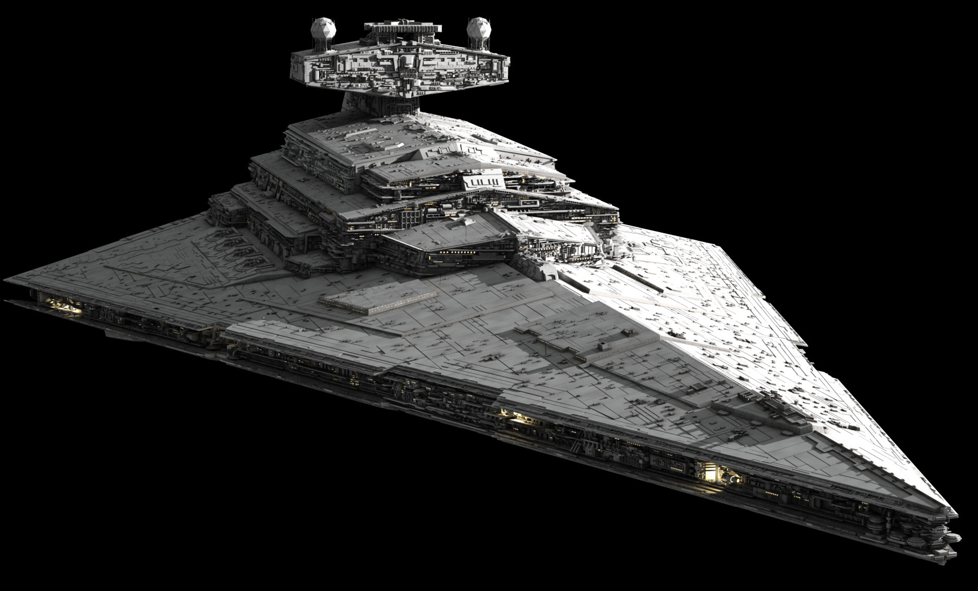
Imperial Star Destroyer
General Reference:
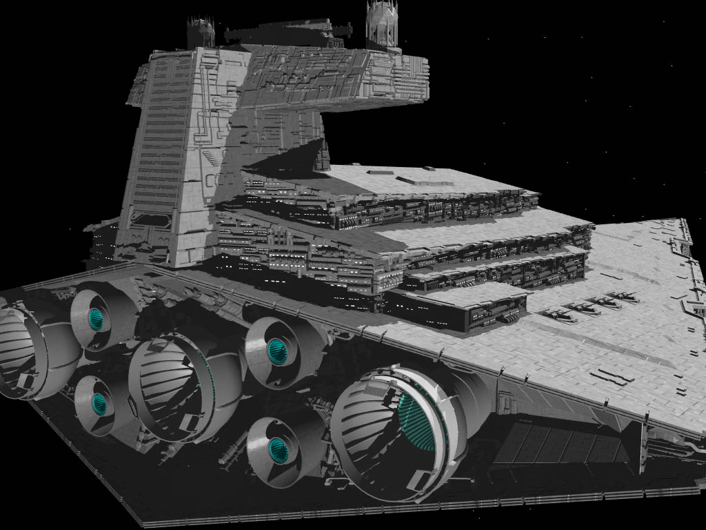
 Rear View:
 Side View:

Z95 Headhunter:
General Reference:
 Underside View:

 (note: Finding reference images for the Headhunter was particularly hard
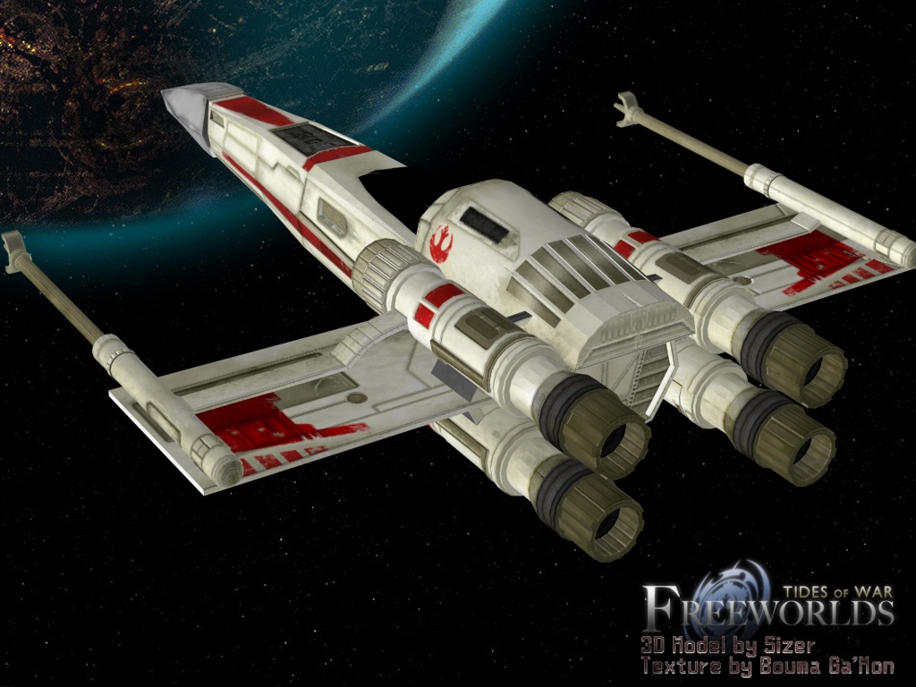
X-Wing:
General Reference:


Imperial Star Destroyer
General Reference:

Z95 Headhunter:
General Reference:


Rear View:
X-Wing:
General Reference:
Rear View:
Extra-Detailed rear view:
2.jpg)
Subscribe to:
Posts (Atom)